for a large picture
|
click on the image
for a large picture |
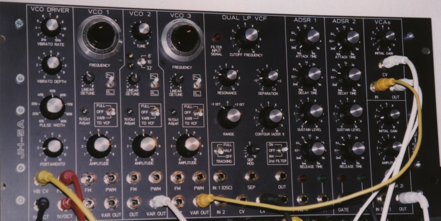
The VCF
The first part I had built was the VCF. I wanted to get that Moog
Modular
Filter sound which I'd heard on several music albums, and wich cannot
be
reproduced with the VCF of a Minimoog, nor with any other Moog filter
I've
heard. (Moog used a lot of different variations of his basic transistor
ladder idea in his various synthesizers. The multitude of Moog filter
clones
add even more variations ...)
I did some very extensive Spice simulation work to find the reason
for this different behaviour. My goal was to find the theory behing the
various parasitic effects of the Moog Modular filter, which are
responsible
for its unique sound. Just building the old circuit with modern
components
does not give the desired result. And any modern clone that doesn't
take
the effects of the Range Switch into account will fail to reproduce the
original, because the Range switch doesn't just transpose the cutoff
frequency
up and down - it also changes other parameters which are important for
the sound.
While I was making these experiments, Bob Moog himself returned to
the synthesizer market and introduced his "Minimoog
Voyager". This will have a pair of LPF filters instead of a single
LPF or a HPF / LPF combination. As I am writing this, I have not seen a
Minimoog Voyager "in the flesh", so I have no idea how this Double LPF
is implemented. But I've made a few simulations and experiments with
various
Dual LPF structures and I found that running two LPF's in parallel and
either adding or subtracting their output signals gives some
interesting
sonic results. So I built a second Moog Modular Style LPF and combined
it to a Dual LPF for what was to become my JH-5A panel. I doubt that
Bob
Moog would go back to his very first VCF circuit for the Voyager, so I
expect my JH-5A VCF to be quite different, even if parts of it were
inspired
by the Voyager. With the "2nd Filter" switch in "off" position, it has
the typical old Moog Modular filter sound. With "2nd Filter" in "on"
position,
it shows the phaser-like double resonance effects which are verbally
described
on the Big Briar page (without any claim to be the same). With "2nd
Filter"
in "INV" position, BPF-like effects are possible. The sound is quite
different
from a classic BPF, however.
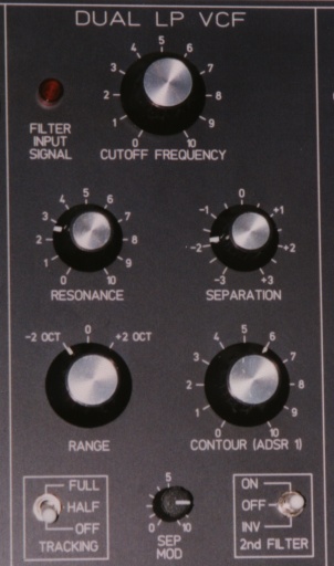 |
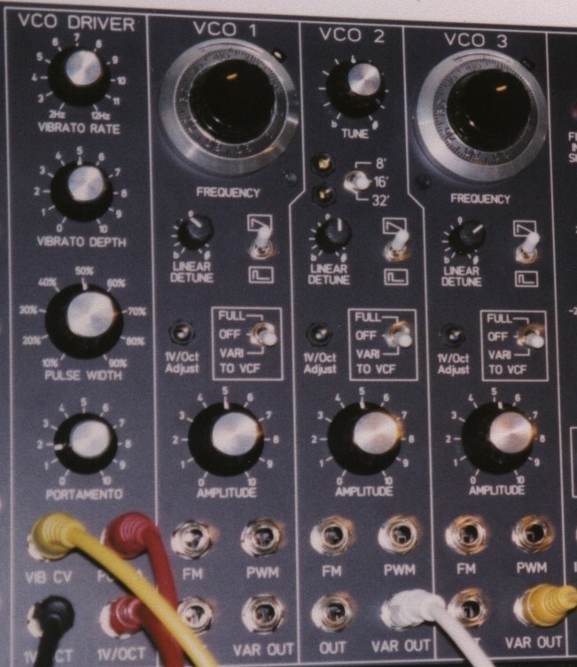
The VCOs
I already have a lot of different VCOs, from the ultra precise MOTM-300
to the lush, but not so well-tracking VCOs of my EMS-Synthi clone. Each
VCO has it's benefits, the CEM3340's (partly under autotune control)
are
the "workhorses" in the OB-8, the Prophet 5 and my own JH-3, the Yamaha
CS-oscillators are more on the "temperamental" side, but still playable
without autotune (the 4 ones in my CS-50 stay better in tune than the 8
ones in my CS-60 ...). The precision of the MOTM VCO is invaluable for
complex audio range modulation patches. I've never heard better drones
than from three EMS VCOs running at almost the same frequency, and
beating
against each other in an ever changing pattern.
My goal was to build a set of VCOs that have the untamed bass range
power of early EMS and Moog VCOs, but which are tracking a keyboard
voltage
over 5 or more octaves nevertheless. I found that "untamed" Beating in
the bass range and controlled beating in higher octaves is not
possible
with standard exponential 1V/Oct oscillators. A good part of that
special
sound of early Moog and EMS oscillators is not because of any
"randomness",
"unstability", "instability" or "noisyness", as so often is said. A
good
deal of their behavior is because of that, but it is not the
whole
story. There are also some very deterministic factors in these old
circuits
which have been unpleasant side effects for the designers back then,
but
which are worth a closer analysis when we're designing a musical VCO
today.
This is implemented in form of three "linear detune" potentiometers on
the JH-5A VCOs.
N EW:
PCBs
for JH-5A VCOs will be availablable in my "Living VCOs" project.
 |
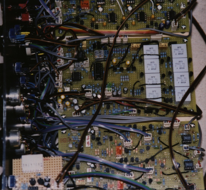
Looking inside
 |
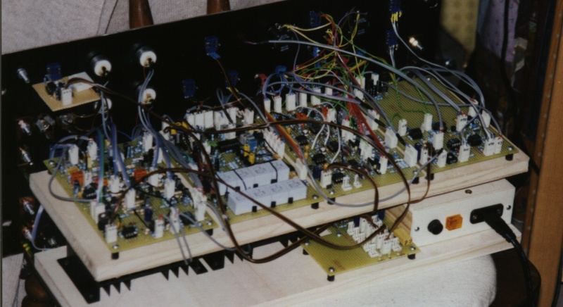 |
Variable Slope HPF
A HPF to complement the JH-5A's Moog-style LPF.
As the LPF is very close to the Moog 904A, a 904B clone would have
been an obvious choice for the HPF. But the 904B was limited to
24dB/Oct
slope, and it did not have a Resonance function.
The HPF of the JH-5B will have variable Slope, even under
voltage
control, and a voltage controlled Resonance.
The two functions are combined - they share one front panel
potentiometer and one CV input.
With the potentiometer in center position ("12 o'clock"), the filter
is very much like a Moog 904B HPF: 24dB slope, no feedback.
Turning potentiometer to the left will gradually decrease the filter
slope. At the ccw end position the slope reaches approx. 6dB/Oct.
Turning the potentiometer to the right will keep the 24dB/Oct slope,
but gradually add feedback or resonance.
The following simulation plot will describe this behaviour better than
a lot of words.
Copyright J. Haible (C) 1996 - 2001