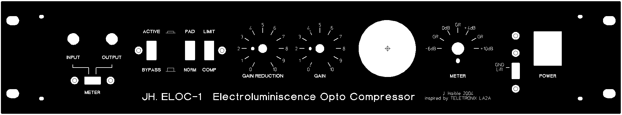
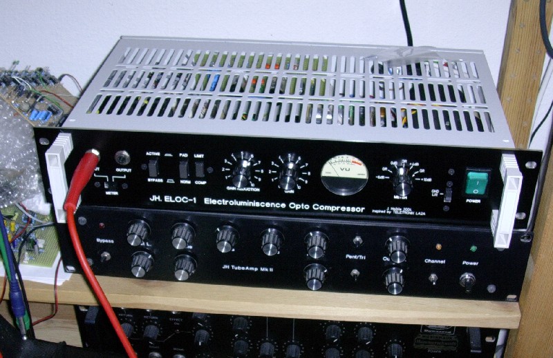
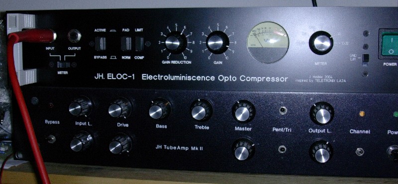
by Jürgen Haible, 2004
Inspired by the classic LA2A and LA3A designs
(Click on image to enlarge)
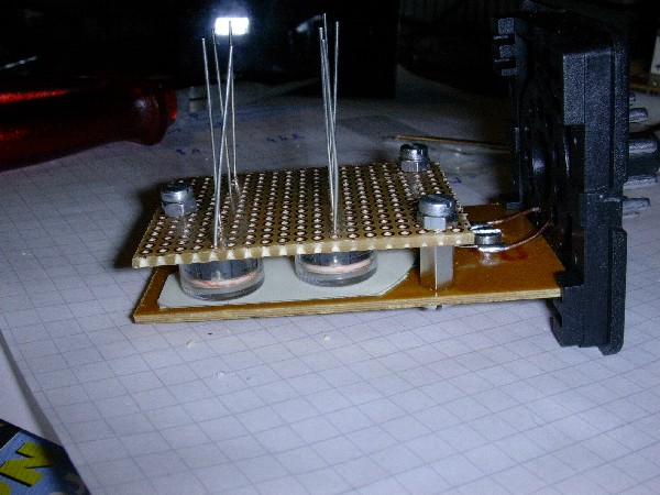

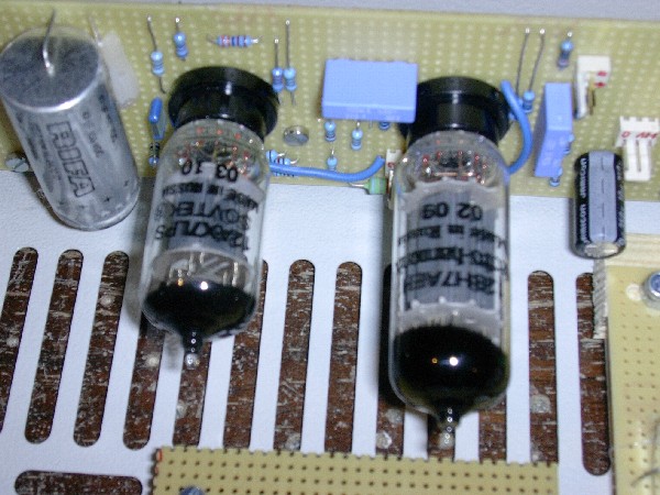
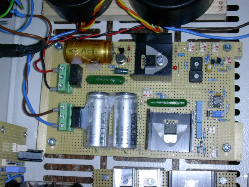
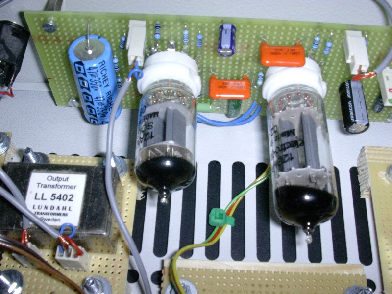
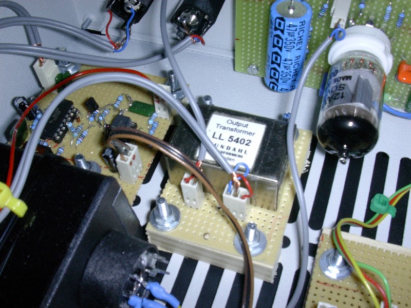
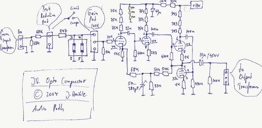
The compressor worked nicely with an audio amp that was close to the original LA2A, except that I didn't like the sound when the amp was overdriven. The tight feedback loop over 3 stages maks the circuit not much different from typical transistor amps: Very low distortion in the linear region, then a sudden unpleasant scratching sound once the maximum output voltage or current is exceeded. I thought I should change this, and the new version has no feedback loop, only two stages (half of a 12AX7 for voltage gain, and the 12BH7 for current gain). Maximum voltage gain is reduced (approx. 60), but still enough for my applications. And the amp now has wonderful soft clipping. Certainly a higher THD in the „linear“ region, too. I don't know if this is good or bad for vocal processing, but it's pure magic for compressing a Fender Rhodes E-Piano sound. I really like it a lot.
Without a feedback loop, low impedance of the White Cathode Follower is even more important than in the old version. OTOH, with the 12AX7 now (softly) reducing the voltage swing at the WCF input anyway, the WCF could be optimised for low output impedance and smooth Class A operation rather than maximising its large signal drive capability.
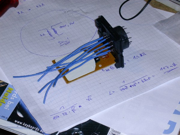
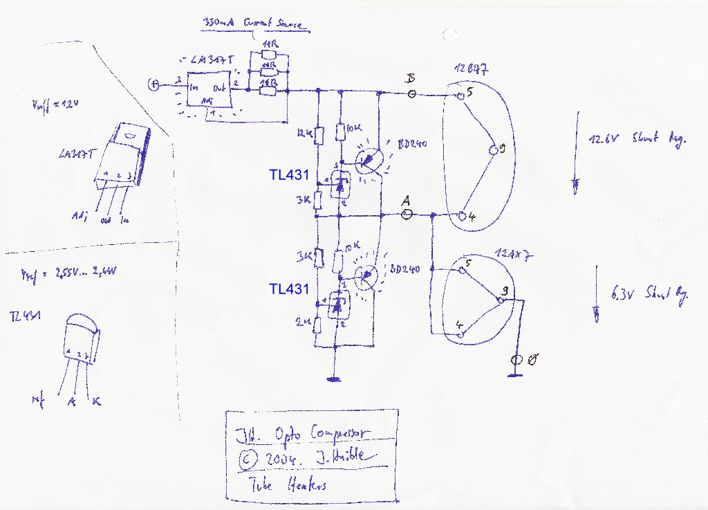
Without a feedback loop, PSRR is much worse than before. It's not enough to filter the voltage gain stage(s); the WCF's supply needs an extra filter stage, too. Funny enough, the previous strong filtering of the 12AX7's supply had a negative effect on PSRR in the new circuit because of phase inversion of the two stages! So I filtered the whole amp with an extra 470R * 47uF time constant, and reduced the filter cap for the 12AX7 to 100nF. I also made a slight change to the PSU to give a slightly higher supply voltage. (My supply voltage was lower than on the original anyway, as I only have 230V AC secondary voltage instead of 250V AC)
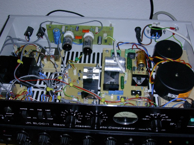
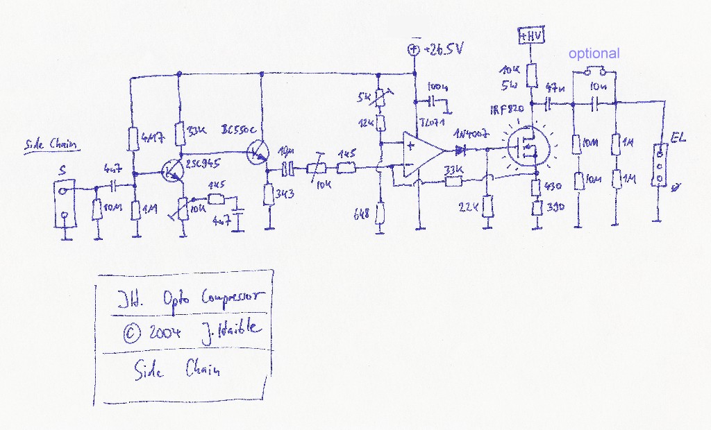
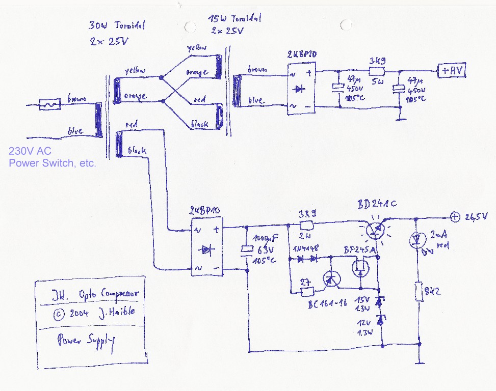
Here are the new circuits:
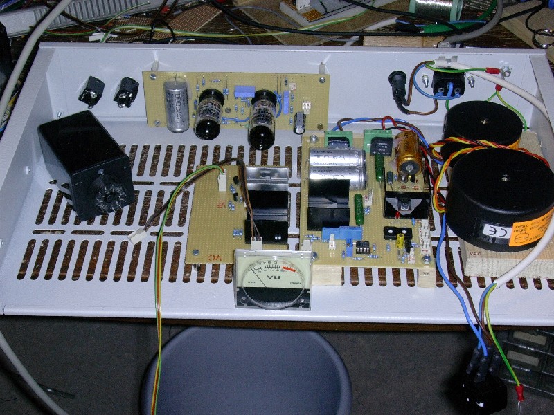
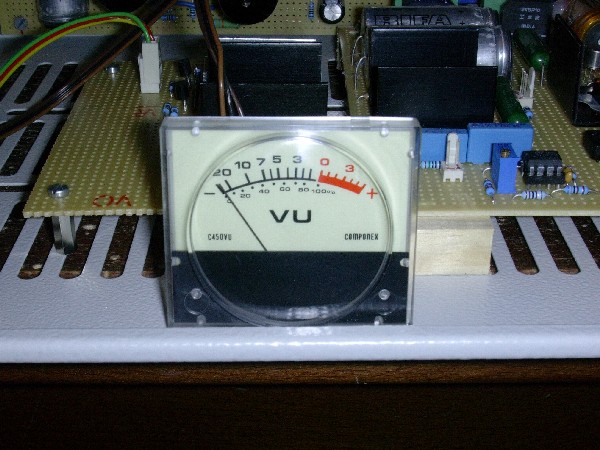
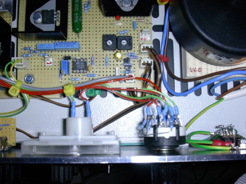
I also made an active (pseudo) VU meter circuit which includes a -6dB range as well as 0dB, +4dB and +10dB (for the meter's 0dB position). Every second switch position is wired to display the Gain Reduction.
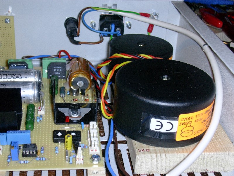
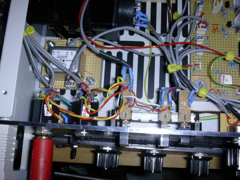
And finally, the interconnections, transformers, true bypass switch and input attenuator switch.
(Click on image to enlarge)
(Click
on image to enlarge)
(click on image to enlarge)
(c) 2004 Jürgen Haible